


A fascinating behaviour of the series RLC circuit is the phenomenon of resonance.
a. Explain Resonance in an LCR circuit.
b. Draw a graphical representation of variation of current amplitude \[{i_m}\] with frequency \[\omega \].
c. What do you mean by sharpness of resonance? Explain it.
Answer
643.2k+ views
Hint: In an LCR circuit, the impedance is given by,
\[Z = \sqrt {{R^2} + {{\left( {{X_L} - {X_C}} \right)}^2}} \]
Q factor is given by,
\[Q = \dfrac{1}{R}\sqrt {\dfrac{L}{C}} \].
Complete step by step solution:
a). Resonance in an LCR circuit:
In a series LCR circuit, electrical resonance is said to occur when the circuit increases current for a given frequency of the origin of alternating supply for which capacitive reaction is equal to the inductive reaction. LCR circuit impedance is low, and thus full current.
In an LCR circuit, the impedance is given by,
\[Z = \sqrt {{R^2} + {{\left( {{X_L} - {X_C}} \right)}^2}} \]
Here, \[R\]is the resistance,
\[{X_L}\] is inductive resistance,
\[{X_C}\] is capacitive resistance.
At resonance in LCR circuit,
\[
{X_L} = {X_C} \\
\omega L = \dfrac{1}{{\omega C}} \\
\]
Therefore, \[\omega = \dfrac{1}{{\sqrt {LC} }}\], known as resonance frequency.
Now, impedance is minimum at resonance,
\[{Z_{\min }} = R\], which means that the current becomes maximum,
\[{I_{\max }} = \dfrac{{{V_{rms}}}}{R}\]
b). Graphical representation of variation of current amplitude \[{i_m}\] with frequency \[\omega \]:
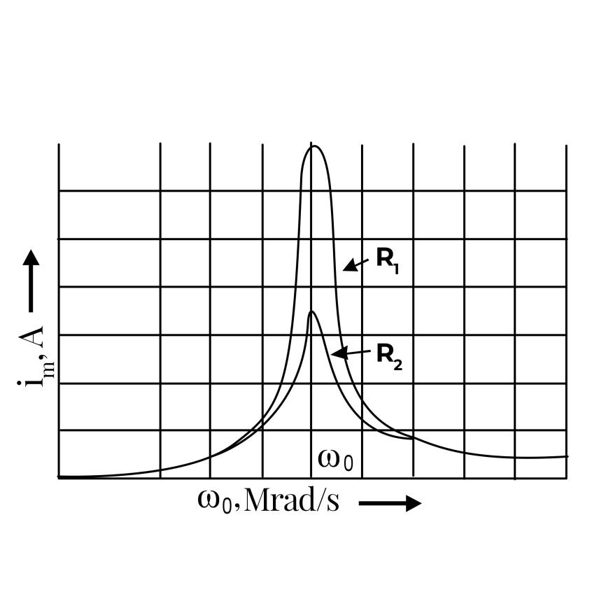
The figure implies the variation of current amplitude \[{i_m}\] with frequency \[\omega \] in LCR circuits of two values of resistance \[{R_1}\] and \[{R_2}\]. Where \[{R_1} > {R_2}\].
c). Sharpness of resonance:
Resonance sharpness depends on an oscillating wave's Q factor that also indicates how quickly the oscillating wave is depleting with respect to time.
There are essentially two things that make resonance sharpness rely on. They are: Amplitude and Damping.
Q factor:
The quality factor or Q factor is a dimensionless function in physics and engineering that specifies how under damped an oscillator or resonator is. It is measured as the number of the maximum energy stored in the resonator during an oscillation period to the energy is lost per period radian.
It is given by, \[Q = \dfrac{1}{R}\sqrt {\dfrac{L}{C}} \].
Note: Impedance of an LCR circuit is given by \[Z = \sqrt {{R^2} + {{\left( {{X_L} - {X_C}} \right)}^2}} \]. In the graphical representation, place current amplitude \[{i_m}\] in vertical axis and frequency \[\omega \]in the horizontal axis respectively.
\[Z = \sqrt {{R^2} + {{\left( {{X_L} - {X_C}} \right)}^2}} \]
Q factor is given by,
\[Q = \dfrac{1}{R}\sqrt {\dfrac{L}{C}} \].
Complete step by step solution:
a). Resonance in an LCR circuit:
In a series LCR circuit, electrical resonance is said to occur when the circuit increases current for a given frequency of the origin of alternating supply for which capacitive reaction is equal to the inductive reaction. LCR circuit impedance is low, and thus full current.
In an LCR circuit, the impedance is given by,
\[Z = \sqrt {{R^2} + {{\left( {{X_L} - {X_C}} \right)}^2}} \]
Here, \[R\]is the resistance,
\[{X_L}\] is inductive resistance,
\[{X_C}\] is capacitive resistance.
At resonance in LCR circuit,
\[
{X_L} = {X_C} \\
\omega L = \dfrac{1}{{\omega C}} \\
\]
Therefore, \[\omega = \dfrac{1}{{\sqrt {LC} }}\], known as resonance frequency.
Now, impedance is minimum at resonance,
\[{Z_{\min }} = R\], which means that the current becomes maximum,
\[{I_{\max }} = \dfrac{{{V_{rms}}}}{R}\]
b). Graphical representation of variation of current amplitude \[{i_m}\] with frequency \[\omega \]:
The figure implies the variation of current amplitude \[{i_m}\] with frequency \[\omega \] in LCR circuits of two values of resistance \[{R_1}\] and \[{R_2}\]. Where \[{R_1} > {R_2}\].
c). Sharpness of resonance:
Resonance sharpness depends on an oscillating wave's Q factor that also indicates how quickly the oscillating wave is depleting with respect to time.
There are essentially two things that make resonance sharpness rely on. They are: Amplitude and Damping.
Q factor:
The quality factor or Q factor is a dimensionless function in physics and engineering that specifies how under damped an oscillator or resonator is. It is measured as the number of the maximum energy stored in the resonator during an oscillation period to the energy is lost per period radian.
It is given by, \[Q = \dfrac{1}{R}\sqrt {\dfrac{L}{C}} \].
Note: Impedance of an LCR circuit is given by \[Z = \sqrt {{R^2} + {{\left( {{X_L} - {X_C}} \right)}^2}} \]. In the graphical representation, place current amplitude \[{i_m}\] in vertical axis and frequency \[\omega \]in the horizontal axis respectively.
Recently Updated Pages
Basicity of sulphurous acid and sulphuric acid are
Master Class 10 Computer Science: Engaging Questions & Answers for Success
Master Class 10 Social Science: Engaging Questions & Answers for Success
Master Class 10 Science: Engaging Questions & Answers for Success
Class 10 Question and Answer - Your Ultimate Solutions Guide
Master Class 10 Maths: Engaging Questions & Answers for Success
Trending doubts
What is the Total Duration of Football Match?
Explain the Treaty of Vienna of 1815 class 10 social science CBSE
In football, which nation is called "La Roja"?
Why is there a time difference of about 5 hours between class 10 social science CBSE
10 examples of evaporation in daily life with explanations
What is the full form of POSCO class 10 social science CBSE